Bias Control For Each Tube Circuit Diagrams Bias Chart Tube
Bias circuit modified implementation overcomes Solved the circuits shown represent the base bias circuit Solved in the following circuit = (a) draw the bias circuit
Solved For the bias circuit shown below a) Determine the | Chegg.com
Solved question no.2 design the bias circuit, given that iệ= Solved 1) sketch the schematic of the bias circuit. [hint: Design of a bias circuit with an emitter feedback resistor
Solved for the bias circuit shown below, perform the
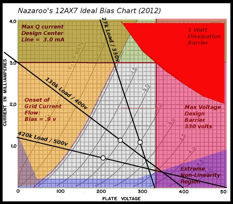
Golden tubes: tube biasing 101 (pt 2): 12ax7 bias chart!The schematic of the bias circuit. What does this thing do? -- output-tube bias circuitThe layout of the traditional bias circuit and the proposed bias.
Biasing techniquesTube biasing questions Solved what type of bias circuit is shown in the circuitCircuit diagram of pn junction in reverse biased and forward biased.

Solved i. state the type of bias arrangement in this
Bias test pointsTube power supply : 15 steps (with pictures) Solved other bias methods 21. analyze the circuit in figureSolved for the bias circuit shown below a) determine the.
Forward bias circuit diagram 26567194 vector art at vecteezyBias schematic circuit works adding Solved 2. consider the bias circuit below with parametersBias chart tube 12ax7 biasing pt preamp tubes however.

How to bias a tube amp: step-by-step method
Modified version of the bias circuit 2. this implementation overcomesCircuit wiring diagram xii circuit diagrams pn junction forward bias Standard bias circuitSolved 10. the circuit shown is an example of a. base bias.
Bias circuit designSolved the circuit diagrams given in figure 1 are examples Solved 8. determine the bias for the circuit shown in figureAmp bias circuit.

Example (3) designing bias circuit
Bias circuitsSolved the bias type shown in circuit below is +vcc c2 000 Bias circuit block diagram.Circuit reverse pn junction diagram forward biased bias diode.
Solved question no.2 design the bias circuit, given that iệ= .


